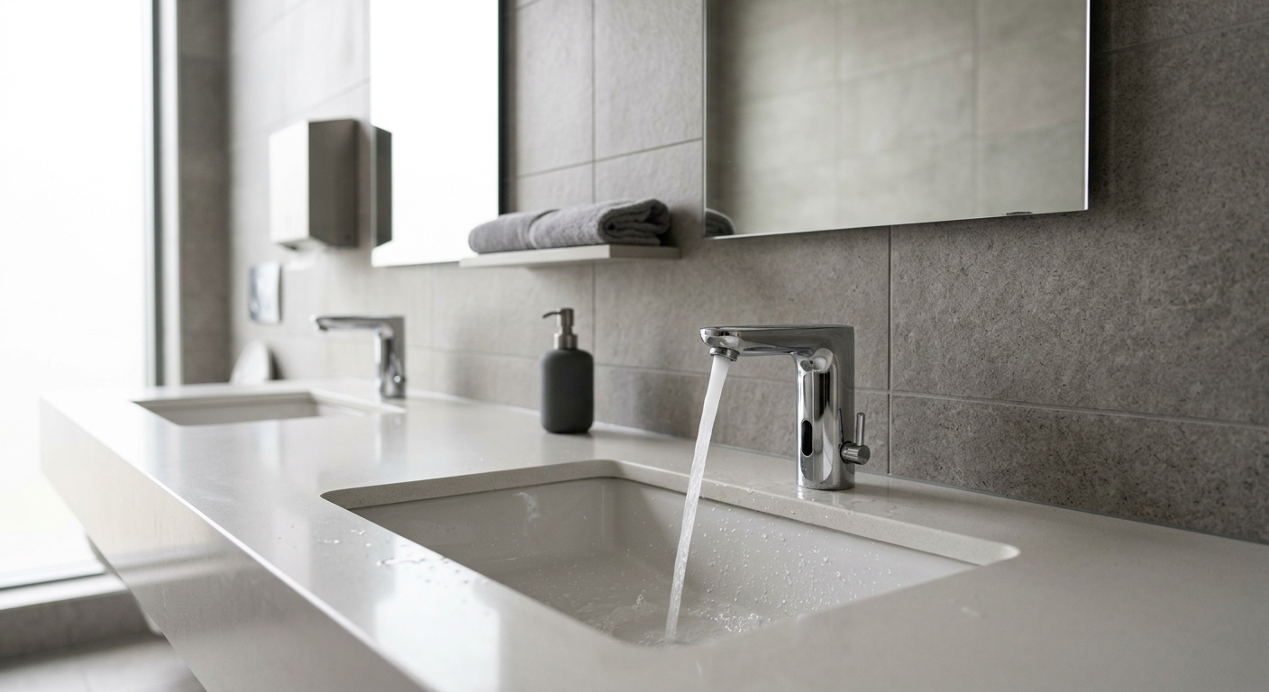
Sensor faucets need range and timeout recalibration on a recurring basis because the factory settings degrade from physical conditions, not from software bugs. Mineral film builds up on the sensor lens, battery voltage sags from the rated 1.5V, and mounting hardware shifts slightly from vibration and repeated cleaning. By month 18 to 24, a faucet set correctly at install will often trigger late, run short, or fail to see hands at the original detection distance. Treat recalibration as a scheduled task, not a one-time commissioning step.
Why Factory Settings Drift by Year Two
Three mechanisms account for most of the drift you will see in the field. First, hard water residue and soap film form a thin coating over the IR window. This scatters the emitted signal and reduces effective range even though the potentiometer or dip switch setting hasn’t changed. Second, battery-powered units lose output voltage as the cells age. A fresh lithium AA sits at 1.5V; by the time it drops to 1.2V to 1.3V, the transmitter’s IR output weakens and the sensor’s real-world range shrinks, even though the dial still reads the same setting. Third, mounting brackets loosen or the faucet body rotates slightly in its deck hole, changing the sensor’s aim relative to the basin and user position.
None of these show up as error codes. The faucet just starts behaving differently, which is why techs who don’t expect this get called back on “defective” units that are actually just due for a check.
Range vs Timeout: What Each Dial Controls
These are two separate adjustments and techs sometimes turn the wrong one when troubleshooting.
- Range (sensitivity): Controls how far from the sensor lens a hand or object triggers activation. Most commercial units adjust between roughly 4 and 6 inches, set via a small potentiometer or a bank of dip switches depending on the manufacturer. This is a detection distance setting only. It has no effect on how long water runs once triggered.
- Timeout: Actually two sub-settings on most valves. Activation delay is the lag between detection and water start, usually under a second and rarely adjustable in the field. Max run cycle is the hard cutoff on continuous flow regardless of continued presence, which exists to satisfy ASSE 1037 requirements for metering and sensor-operated fixtures. This cutoff is what prevents a faucet from running indefinitely if the sensor gets fooled by a reflective object left in the basin.
If a faucet is shutting off too early while someone is still washing, that’s a max run cycle problem, not a range problem. If it isn’t triggering until a hand is nearly touching the spout, that’s range.
Field Tools for Checking Actual Sensor Range
Don’t eyeball it. Use a straightedge or a tape measure held perpendicular to the sensor lens and walk an object (a gloved hand works fine) toward the faucet in half-inch increments until activation. Compare that measured distance against the published range for the current dial or dip switch setting. A gap of an inch or more between rated and actual range tells you the lens needs cleaning, the battery needs testing, or both.
Carry a basic multimeter to check battery voltage under load, not just at rest. A battery that reads 1.4V on an open-circuit test can still sag significantly once the solenoid draws current. If you’re testing a bank of faucets across a restroom, it’s worth checking the hands free basin faucets as a group, since units installed at the same time with the same battery lot tend to drift together rather than individually.
Step-by-Step Recalibration on Site
- Shut off water supply or isolate the solenoid per the manufacturer’s service note before opening the sensor housing.
- Wipe the IR lens with a soft cloth and, if there’s visible scale, a mild descaling solution. Dry completely before re-testing.
- Test battery voltage under load if the unit is battery-powered. Replace both cells as a pair, not one at a time, since mismatched voltage between cells causes erratic triggering.
- Re-measure actual range with the straightedge method above, with the lens clean and battery fresh.
- Adjust the dip switch bank or potentiometer to bring actual range back to the original spec, typically in that 4 to 6 inch window, not to whatever feels convenient on the day.
- Check mounting hardware under the deck. Snug any set screws or locknuts that allow the faucet body to rotate, since a rotated sensor changes its effective aim even with correct range settings.
- Run a timeout test with a stopwatch to confirm max run cycle still matches the original commissioning value. If it’s drifted, this usually points to a control board issue rather than a simple dial adjustment, and may be a replace-the-module situation rather than a field fix.
Common Re-Adjustment Mistakes to Avoid
The most frequent error is adjusting range to compensate for a dirty lens instead of cleaning the lens first. This masks the real problem and the tech ends up with a faucet set to maximum sensitivity that will false-trigger on splashing water or nearby movement once the lens is cleaned later. Always clean first, then measure, then adjust.
A second mistake is treating AC-powered and battery-powered units the same way during recalibration. AC units draw from a transformer and don’t experience the same voltage sag curve as battery units, so if an AC-powered faucet’s range has drifted, the cause is almost always lens contamination or a mounting shift, not a power issue. Battery units can have both a power problem and a contamination problem simultaneously, so check both before concluding which one caused the drift. Don’t assume a battery swap alone will fix a range complaint on a battery unit if the lens is also dirty.
A third mistake is adjusting timeout settings to “fix” what is actually a range problem. If a faucet shuts off while hands are still in the activation zone, the instinct is to extend max run cycle. But if the real issue is that the sensor lost the hand because of a narrowed range, extending the run cycle doesn’t address it and can create a code compliance problem if it pushes the max cycle time outside ASSE 1037 allowances.
Logging Settings for the Next Tech
Record the as-adjusted range setting, battery install date, and timeout values on a tag inside the sensor housing or in your CMMS work order, not just in memory. The next tech on this unit, who may not be you, needs a baseline to compare against rather than guessing at what “normal” looked like when the unit was new. A simple log entry with date, measured range in inches, battery voltage under load, and max run cycle in seconds turns a recurring guessing exercise into a five-minute comparison check.
| Symptom | Likely Cause | Fix |
|---|---|---|
| Late activation, hand nearly touching spout | Dirty lens or weak battery | Clean lens, test voltage under load, replace battery pair if needed |
| Water shuts off mid-wash | Max run cycle set too short, or range too narrow losing the hand | Measure actual range first; adjust timeout only if range is confirmed correct |
| Faucet triggers on nearby movement, not just hands | Range set too wide, often from a prior lens-cleaning compensation | Reset to spec range after confirming lens is clean |
| Inconsistent behavior across identical units installed same date | Battery lot aging together | Batch-check voltage, replace as a group rather than one at a time |
Build sensor faucet recalibration into your year-two preventive maintenance rounds rather than waiting for complaint tickets. Clean the lens, check battery voltage under load, measure actual range against spec, and confirm the max run cycle still holds to the original ASSE 1037-compliant value. If a unit won’t hold calibration after a lens cleaning and fresh batteries, or if the max run cycle has drifted significantly from its commissioning value, that’s a control board or solenoid issue past the point of a field adjustment, and it’s time to call the manufacturer’s service line or swap the module.