Tag: commercial plumbing

  • Sensor Shower Head Still Dripping? Year-Two Valve Fixes

    A sensor shower head that keeps dripping after shutoff is almost never a washer problem. On a solenoid-actuated valve, residual drip points to one of three failure modes: a worn diaphragm that no longer seats fully, debris lodged on the valve seat, or a failed check valve letting residual line pressure weep past the solenoid. Diagnosing which one requires pulling the valve body, not the shower head.

    Why Sensor Showers Drip Differently Than Manual Ones

    A manual shower valve drips because a washer or cartridge wears against a fixed seat under hand-applied torque. A sensor shower uses a solenoid-actuated valve that opens and closes electrically, either on 24VAC transformer power or a battery-driven actuator, and the shutoff depends on a diaphragm or plunger sealing fully against the seat when the coil de-energizes. There’s no manual override torque to force a tight seal. If the diaphragm has taken a set, or if there’s a particle sitting on the seat, the valve closes but doesn’t seal, and water weeps through at line pressure. That’s a mechanical or electrical fault inside the valve body, not a worn consumer part you replace with a hardware-store kit.

    Solenoid Diaphragm Wear at the Year-Two Mark

    Most commercial sensor shower valves use an elastomer diaphragm that flexes thousands of times per day in a high-use locker room. Manufacturers typically rate these for a cycle count, but in practice the diaphragm starts to lose its seal integrity around the eighteen-to-twenty-four-month mark in heavy-use facilities, faster if the water supply runs hot and chlorinated at a higher concentration than the diaphragm compound tolerates well. The failure mode is a soft, pitted, or slightly swollen diaphragm face that no longer closes flush against the seat. You’ll see a steady drip or a thin stream rather than the typical intermittent drip of debris-related leaks.

    Replacement means sourcing the OEM diaphragm kit for that specific valve model, not a generic cartridge. Cross-brand substitution is unreliable because seat geometry and diaphragm durometer vary by manufacturer. Pull the solenoid coil housing, inspect the diaphragm face under good light, and compare it against a new kit component before you commit to the repair. If the diaphragm looks glazed, cracked at the fold line, or has a visible flat spot from sitting in one position, replace it.

    Debris and Scale on the Valve Seat

    The second most common year-two call is debris sitting on the valve seat, usually scale fragments, pipe dope, or sediment from a water heater anode breakdown. This is where the inline strainer or Y-filter earns its keep. Most commercial sensor valves spec a strainer immediately upstream of the solenoid body specifically because the orifice and seat clearances are tight enough that ordinary municipal sediment can hold the valve open a few thousandths of an inch, enough to drip but not enough to run a full stream.

    If the strainer hasn’t been serviced since install, that’s your first suspect. A neglected Y-filter will pass enough fine debris over time to scar the seat itself, which turns a five-minute cleaning job into a seat replacement or full valve swap. Check the strainer basket before you disassemble anything else. If it is packed with debris, clean it, flush the line, and re-test before you assume diaphragm failure.

    Testing the Check Valve and Flow Control

    If the diaphragm looks fine and the strainer is clean but the drip persists, test the integral check valve. These valves are there to prevent backflow and to isolate the solenoid chamber from residual static pressure in the supply line. A failed check valve lets that residual head pressure bleed past the solenoid seal even when the diaphragm itself is sealing correctly, which produces a slow weep that looks identical to diaphragm wear until you isolate the components.

    Field test: shut the supply stop, open the valve body, and pressurize the downstream side independently if your test rig allows it. A good check valve holds; a failed one leaks back immediately. While you have the valve open, confirm the flow restrictor is still in place and rated correctly. Code caps shower head flow at 2.5 GPM federally, with California and a few other jurisdictions at 1.8 GPM, and a missing or swapped restrictor won’t cause a drip by itself but it will throw off your diagnostic baseline if you’re trying to measure weep rate against expected flow.

    Step-by-Step Field Diagnosis and Repair

    1. Isolate the supply stop and confirm zero flow at the head before opening anything.
    2. Pull the strainer or Y-filter screen and inspect for sediment, scale, or thread tape fragments. Clean or replace as needed.
    3. Remove the solenoid coil housing and inspect the diaphragm face for pitting, swelling, or a visible flat spot.
    4. If the diaphragm looks sound, test the check valve in isolation using a hand pump or your facility’s test gauge setup.
    5. Confirm the flow restrictor matches spec, 2.5 GPM or lower depending on jurisdiction, so your weep-rate testing is accurate.
    6. Reassemble, restore line pressure gradually, and run a full open-close cycle at least five times to confirm the seal holds under repeated actuation, not just on the first cycle.

    Document the actuator type (24VAC transformer or battery) and valve model before you order parts. Cross-compatibility between manufacturers is poor, and ordering the wrong diaphragm kit means a second truck roll.

    Symptom Likely Cause Fix
    Steady drip, no debris in strainer Worn solenoid diaphragm Replace OEM diaphragm kit
    Intermittent drip, varies after flushing Debris on valve seat Clean strainer, flush line, inspect seat
    Slow weep even with new diaphragm installed Failed check valve Replace check valve, retest under isolated pressure
    Flow rate reads high, drip plus weak shutoff Missing or wrong flow restrictor Install correct-rated restrictor per code

    Preventing Repeat Calls on Locker Room Units

    High-cycle installations like gym and locker room showers wear diaphragms faster than a single-occupancy restroom, so a fixed annual inspection schedule is false economy. Set strainer cleaning on a quarterly cycle in high-traffic facilities and inspect diaphragm condition annually, moving to semi-annual once a building passes the two-year mark on original components. Keep a stock diaphragm kit and check valve on the shelf for your most common valve model so a confirmed failure doesn’t turn into a multi-day service outage while parts ship.

    When you’re replacing a valve body wholesale rather than servicing it, it’s worth specifying the full assembly rather than sourcing individual components piecemeal, particularly on jobs where you’re also swapping the head and trim. Looking at complete shower systems with matched valve, head, and body jet components simplifies future service because every part in the assembly is rated for the same flow and pressure, which keeps your diagnostic baseline consistent across the unit.

    If you’ve worked through strainer, diaphragm, and check valve and the drip persists, the next step is pressure-testing the supply line itself for static pressure above the valve’s rated range, since diaphragms and check valves both fail prematurely under chronic overpressure. A valve rated for standard commercial supply pressure won’t hold a reliable seal if the building’s static pressure runs high and no pressure-reducing valve is installed upstream. That’s a building-system fix, not a fixture repair, and it’s worth flagging to the engineer of record if you’re seeing repeat failures across multiple units on the same riser.
  • Recalibrating Sensor Range and Timeout After Year One

    Sensor faucets need range and timeout recalibration on a recurring basis because the factory settings degrade from physical conditions, not from software bugs. Mineral film builds up on the sensor lens, battery voltage sags from the rated 1.5V, and mounting hardware shifts slightly from vibration and repeated cleaning. By month 18 to 24, a faucet set correctly at install will often trigger late, run short, or fail to see hands at the original detection distance. Treat recalibration as a scheduled task, not a one-time commissioning step.

    Why Factory Settings Drift by Year Two

    Three mechanisms account for most of the drift you will see in the field. First, hard water residue and soap film form a thin coating over the IR window. This scatters the emitted signal and reduces effective range even though the potentiometer or dip switch setting hasn’t changed. Second, battery-powered units lose output voltage as the cells age. A fresh lithium AA sits at 1.5V; by the time it drops to 1.2V to 1.3V, the transmitter’s IR output weakens and the sensor’s real-world range shrinks, even though the dial still reads the same setting. Third, mounting brackets loosen or the faucet body rotates slightly in its deck hole, changing the sensor’s aim relative to the basin and user position.

    None of these show up as error codes. The faucet just starts behaving differently, which is why techs who don’t expect this get called back on “defective” units that are actually just due for a check.

    Range vs Timeout: What Each Dial Controls

    These are two separate adjustments and techs sometimes turn the wrong one when troubleshooting.

    • Range (sensitivity): Controls how far from the sensor lens a hand or object triggers activation. Most commercial units adjust between roughly 4 and 6 inches, set via a small potentiometer or a bank of dip switches depending on the manufacturer. This is a detection distance setting only. It has no effect on how long water runs once triggered.
    • Timeout: Actually two sub-settings on most valves. Activation delay is the lag between detection and water start, usually under a second and rarely adjustable in the field. Max run cycle is the hard cutoff on continuous flow regardless of continued presence, which exists to satisfy ASSE 1037 requirements for metering and sensor-operated fixtures. This cutoff is what prevents a faucet from running indefinitely if the sensor gets fooled by a reflective object left in the basin.

    If a faucet is shutting off too early while someone is still washing, that’s a max run cycle problem, not a range problem. If it isn’t triggering until a hand is nearly touching the spout, that’s range.

    Field Tools for Checking Actual Sensor Range

    Don’t eyeball it. Use a straightedge or a tape measure held perpendicular to the sensor lens and walk an object (a gloved hand works fine) toward the faucet in half-inch increments until activation. Compare that measured distance against the published range for the current dial or dip switch setting. A gap of an inch or more between rated and actual range tells you the lens needs cleaning, the battery needs testing, or both.

    Carry a basic multimeter to check battery voltage under load, not just at rest. A battery that reads 1.4V on an open-circuit test can still sag significantly once the solenoid draws current. If you’re testing a bank of faucets across a restroom, it’s worth checking the hands free basin faucets as a group, since units installed at the same time with the same battery lot tend to drift together rather than individually.

    Step-by-Step Recalibration on Site

    1. Shut off water supply or isolate the solenoid per the manufacturer’s service note before opening the sensor housing.
    2. Wipe the IR lens with a soft cloth and, if there’s visible scale, a mild descaling solution. Dry completely before re-testing.
    3. Test battery voltage under load if the unit is battery-powered. Replace both cells as a pair, not one at a time, since mismatched voltage between cells causes erratic triggering.
    4. Re-measure actual range with the straightedge method above, with the lens clean and battery fresh.
    5. Adjust the dip switch bank or potentiometer to bring actual range back to the original spec, typically in that 4 to 6 inch window, not to whatever feels convenient on the day.
    6. Check mounting hardware under the deck. Snug any set screws or locknuts that allow the faucet body to rotate, since a rotated sensor changes its effective aim even with correct range settings.
    7. Run a timeout test with a stopwatch to confirm max run cycle still matches the original commissioning value. If it’s drifted, this usually points to a control board issue rather than a simple dial adjustment, and may be a replace-the-module situation rather than a field fix.

    Common Re-Adjustment Mistakes to Avoid

    The most frequent error is adjusting range to compensate for a dirty lens instead of cleaning the lens first. This masks the real problem and the tech ends up with a faucet set to maximum sensitivity that will false-trigger on splashing water or nearby movement once the lens is cleaned later. Always clean first, then measure, then adjust.

    A second mistake is treating AC-powered and battery-powered units the same way during recalibration. AC units draw from a transformer and don’t experience the same voltage sag curve as battery units, so if an AC-powered faucet’s range has drifted, the cause is almost always lens contamination or a mounting shift, not a power issue. Battery units can have both a power problem and a contamination problem simultaneously, so check both before concluding which one caused the drift. Don’t assume a battery swap alone will fix a range complaint on a battery unit if the lens is also dirty.

    A third mistake is adjusting timeout settings to “fix” what is actually a range problem. If a faucet shuts off while hands are still in the activation zone, the instinct is to extend max run cycle. But if the real issue is that the sensor lost the hand because of a narrowed range, extending the run cycle doesn’t address it and can create a code compliance problem if it pushes the max cycle time outside ASSE 1037 allowances.

    Logging Settings for the Next Tech

    Record the as-adjusted range setting, battery install date, and timeout values on a tag inside the sensor housing or in your CMMS work order, not just in memory. The next tech on this unit, who may not be you, needs a baseline to compare against rather than guessing at what “normal” looked like when the unit was new. A simple log entry with date, measured range in inches, battery voltage under load, and max run cycle in seconds turns a recurring guessing exercise into a five-minute comparison check.

    Symptom Likely Cause Fix
    Late activation, hand nearly touching spout Dirty lens or weak battery Clean lens, test voltage under load, replace battery pair if needed
    Water shuts off mid-wash Max run cycle set too short, or range too narrow losing the hand Measure actual range first; adjust timeout only if range is confirmed correct
    Faucet triggers on nearby movement, not just hands Range set too wide, often from a prior lens-cleaning compensation Reset to spec range after confirming lens is clean
    Inconsistent behavior across identical units installed same date Battery lot aging together Batch-check voltage, replace as a group rather than one at a time

    Build sensor faucet recalibration into your year-two preventive maintenance rounds rather than waiting for complaint tickets. Clean the lens, check battery voltage under load, measure actual range against spec, and confirm the max run cycle still holds to the original ASSE 1037-compliant value. If a unit won’t hold calibration after a lens cleaning and fresh batteries, or if the max run cycle has drifted significantly from its commissioning value, that’s a control board or solenoid issue past the point of a field adjustment, and it’s time to call the manufacturer’s service line or swap the module.

  • Solenoid Valve Failure in Year Two: A Field Diagnosis Guide

    Solenoid Valve Failure in Year Two: A Field Diagnosis Guide

    Solenoid valves in sensor faucets fail at the 12 to 24 month mark almost always for the same three reasons: mineral scale binding the diaphragm, corrosion at the low-voltage connector, and a clogged inline strainer starving the valve of flow. Before you order a replacement solenoid, run the multimeter tests below. A large share of “dead solenoid” service calls turn out to be a bad connector or a battery pack nobody replaced.

    Why Year Two Is the Failure Window

    Year one rarely produces failures because everything is new: seals are seated, screens are clean, contacts aren’t oxidized. By month 12 to 24, three things have accumulated. Mineral scale from hard water has built up on the diaphragm and pilot orifice. Low-voltage connectors, especially those in humid under-sink environments, have started to corrode at the crimp or spade terminal. And the inline strainer, which is doing its job, has collected enough sediment to restrict flow to the point the valve can’t fully open even when it’s energized correctly.

    This is a wear-and-water-quality problem, not a manufacturing defect problem. Buildings on well water or unsoftened municipal supply with high hardness will see this window compress toward 12 months. Buildings on softened water or low-mineral supply can stretch past 24 months before symptoms appear.

    Solenoid Failure vs Sensor Failure Symptoms

    The fastest way to waste a service call is replacing a solenoid when the sensor or transformer is the actual problem. The symptom sets overlap just enough to cause confusion in the field.

    Symptom Likely Cause
    No water, no LED activity on sensor Power supply: dead battery or failed transformer
    LED responds to hand presence, no water Solenoid valve or wiring between sensor and valve
    Water trickles but won’t reach full flow Clogged strainer or partially blocked diaphragm
    Water runs continuously, won’t shut off Debris holding diaphragm open, or failed sensor board
    Intermittent operation, works sometimes Corroded connector or loose low-voltage wiring

    The rule of thumb: if the sensor LED is responding correctly to hand movement but no water follows, the problem is downstream of the sensor board. That isolates it to the solenoid, its wiring, or its power feed, and rules out a sensor eye issue entirely.

    Three Common Failure Points in the Field

    Once you’ve isolated the fault to the solenoid side, it’s almost always one of three things.

    • Mineral-clogged diaphragm. Scale builds on the diaphragm and pilot orifice, preventing it from lifting fully or seating fully. This shows up as reduced flow, slow response, or a valve that won’t close and drips after use.
    • Corroded low-voltage connector. The connector between the solenoid coil leads and the control wiring sits in a damp cabinet environment. Spade connectors and crimped splices corrode over time, especially where dissimilar metals are in contact. This produces intermittent operation or complete failure that looks electrical because it is.
    • Degraded strainer screen. The inline strainer, typically a 100-mesh screen, is there to protect the solenoid’s small orifices from sediment. When it loads up with scale and debris it restricts flow before the water ever reaches the valve, and techs sometimes misdiagnose this as valve failure because the symptom (weak or no flow) looks identical.

    Multimeter Test Sequence for Diagnosis

    Before pulling the solenoid, confirm power is actually reaching it and that the coil itself is intact. Solenoids on these faucets run on 6VDC from battery packs or 24VAC from a step-down transformer, depending on the installation. Test procedure differs slightly by power type but the logic is the same.

    • Step 1: Confirm supply voltage at the source. For battery-powered units, check the battery pack under load, not just static voltage. A battery can read near-nominal voltage with a meter and still sag to nothing under the momentary draw the solenoid needs. For transformer-fed units, check output at the transformer terminals: expect 24VAC nominal, and flag anything more than about 10 percent off.
    • Step 2: Check voltage at the solenoid connector during an activation cycle. Trigger the sensor and read voltage at the connector leads. If you get correct voltage here but the valve doesn’t open, the fault is in the valve itself, not the wiring or power supply.
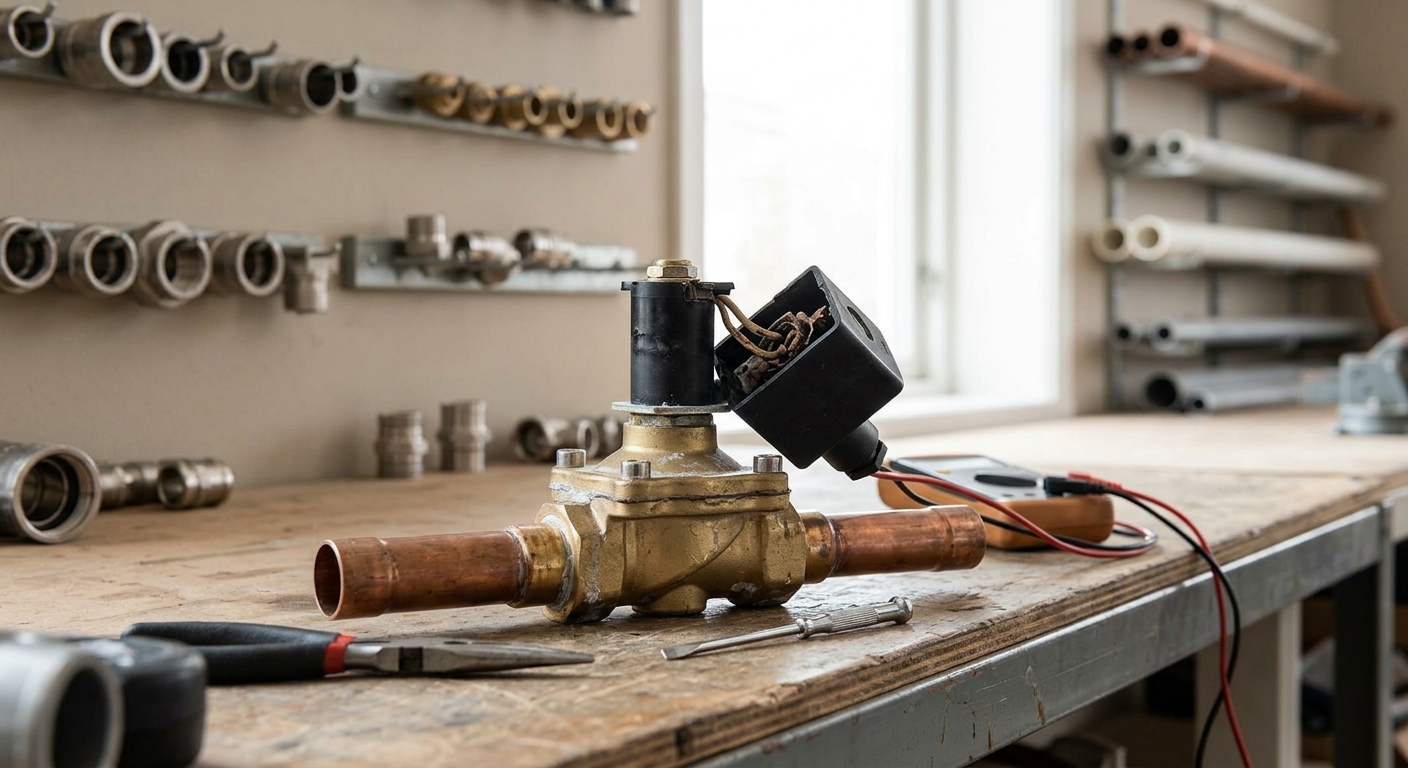
    • Step 3: Test coil continuity and voltage at the connector before replacing the valve. With power disconnected, measure resistance across the coil leads. An open circuit (infinite resistance) means a burned-out coil. A reading of zero or near-zero suggests a shorted coil. Either result confirms the solenoid itself has failed electrically, as opposed to being mechanically stuck from scale.
    • Step 4: If voltage and continuity both check out, suspect mechanical blockage. A solenoid that has correct voltage and healthy coil resistance but still won’t open or close fully is almost certainly blocked by scale or debris on the diaphragm, not electrically dead.

    Document these readings before you disassemble anything. If the part turns out to be under any manufacturer coverage, having voltage and continuity readings on hand supports the claim and speeds up the exchange.

    Rebuild the Valve or Replace It

    Once you’ve confirmed the solenoid is the actual point of failure, the next decision is rebuild versus replace. This depends on what you found in the test sequence and what’s available for that valve.

    If the coil tested fine and the failure is mechanical (scale-bound diaphragm, debris in the orifice), a rebuild kit with a new diaphragm and seals is usually the more economical fix and can often be done in under 20 minutes once the valve is off. Clean the valve body and the strainer screen at the same time, since a fresh diaphragm behind a clogged strainer just fails again on the same timeline.

    If the coil failed electrically (open or shorted), replace the solenoid assembly rather than attempting a coil repair. Rewinding or repairing a coil in the field isn’t practical, and coil assemblies are typically sold as a unit.

    For vanity and basin installations where you’re already accessing the plumbing, it’s worth confirming the aerator and supply connections at the same time. Most of these units connect on a standard 1/2 inch NPT supply, which makes cross-referencing replacement parts or upgrading to a different thermostatic shower systems fixture in a nearby stall straightforward if the building is standardizing on one product line.

    Maintenance Interval to Prevent Repeat Failures

    The single highest-leverage maintenance task is strainer cleaning, not solenoid replacement. A strainer inspection and cleaning on a 6 to 12 month interval, adjusted for local water hardness, prevents the majority of scale-related solenoid problems before they start. Buildings on hard water or well supply should default to the shorter end of that interval.

    At the same visit, inspect the low-voltage connector for corrosion and reseat or replace it if there’s visible oxidation. This is a five-minute check that prevents the intermittent-failure service calls that are hardest to diagnose after the fact.

    Next service call on one of these units: run the four-step voltage and continuity sequence before you open a parts catalog. If voltage and coil resistance both check out, you’re looking at a rebuild kit and a strainer cleaning, not a new valve. If either test fails, order the solenoid assembly and inspect the connector while you’re in there, since a corroded connector on an old valve will just as easily corrode the connector on a new one.