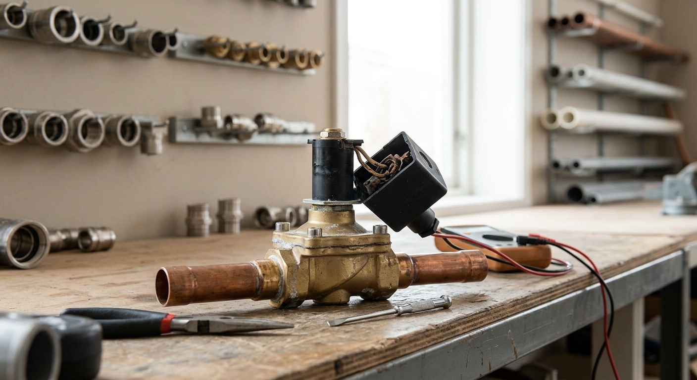
Solenoid valves in sensor faucets fail at the 12 to 24 month mark almost always for the same three reasons: mineral scale binding the diaphragm, corrosion at the low-voltage connector, and a clogged inline strainer starving the valve of flow. Before you order a replacement solenoid, run the multimeter tests below. A large share of “dead solenoid” service calls turn out to be a bad connector or a battery pack nobody replaced.
Why Year Two Is the Failure Window
Year one rarely produces failures because everything is new: seals are seated, screens are clean, contacts aren’t oxidized. By month 12 to 24, three things have accumulated. Mineral scale from hard water has built up on the diaphragm and pilot orifice. Low-voltage connectors, especially those in humid under-sink environments, have started to corrode at the crimp or spade terminal. And the inline strainer, which is doing its job, has collected enough sediment to restrict flow to the point the valve can’t fully open even when it’s energized correctly.
This is a wear-and-water-quality problem, not a manufacturing defect problem. Buildings on well water or unsoftened municipal supply with high hardness will see this window compress toward 12 months. Buildings on softened water or low-mineral supply can stretch past 24 months before symptoms appear.
Solenoid Failure vs Sensor Failure Symptoms
The fastest way to waste a service call is replacing a solenoid when the sensor or transformer is the actual problem. The symptom sets overlap just enough to cause confusion in the field.
| Symptom | Likely Cause |
|---|---|
| No water, no LED activity on sensor | Power supply: dead battery or failed transformer |
| LED responds to hand presence, no water | Solenoid valve or wiring between sensor and valve |
| Water trickles but won’t reach full flow | Clogged strainer or partially blocked diaphragm |
| Water runs continuously, won’t shut off | Debris holding diaphragm open, or failed sensor board |
| Intermittent operation, works sometimes | Corroded connector or loose low-voltage wiring |
The rule of thumb: if the sensor LED is responding correctly to hand movement but no water follows, the problem is downstream of the sensor board. That isolates it to the solenoid, its wiring, or its power feed, and rules out a sensor eye issue entirely.
Three Common Failure Points in the Field
Once you’ve isolated the fault to the solenoid side, it’s almost always one of three things.
- Mineral-clogged diaphragm. Scale builds on the diaphragm and pilot orifice, preventing it from lifting fully or seating fully. This shows up as reduced flow, slow response, or a valve that won’t close and drips after use.
- Corroded low-voltage connector. The connector between the solenoid coil leads and the control wiring sits in a damp cabinet environment. Spade connectors and crimped splices corrode over time, especially where dissimilar metals are in contact. This produces intermittent operation or complete failure that looks electrical because it is.
- Degraded strainer screen. The inline strainer, typically a 100-mesh screen, is there to protect the solenoid’s small orifices from sediment. When it loads up with scale and debris it restricts flow before the water ever reaches the valve, and techs sometimes misdiagnose this as valve failure because the symptom (weak or no flow) looks identical.
Multimeter Test Sequence for Diagnosis
Before pulling the solenoid, confirm power is actually reaching it and that the coil itself is intact. Solenoids on these faucets run on 6VDC from battery packs or 24VAC from a step-down transformer, depending on the installation. Test procedure differs slightly by power type but the logic is the same.
- Step 1: Confirm supply voltage at the source. For battery-powered units, check the battery pack under load, not just static voltage. A battery can read near-nominal voltage with a meter and still sag to nothing under the momentary draw the solenoid needs. For transformer-fed units, check output at the transformer terminals: expect 24VAC nominal, and flag anything more than about 10 percent off.
- Step 2: Check voltage at the solenoid connector during an activation cycle. Trigger the sensor and read voltage at the connector leads. If you get correct voltage here but the valve doesn’t open, the fault is in the valve itself, not the wiring or power supply.
- Step 3: Test coil continuity and voltage at the connector before replacing the valve. With power disconnected, measure resistance across the coil leads. An open circuit (infinite resistance) means a burned-out coil. A reading of zero or near-zero suggests a shorted coil. Either result confirms the solenoid itself has failed electrically, as opposed to being mechanically stuck from scale.
- Step 4: If voltage and continuity both check out, suspect mechanical blockage. A solenoid that has correct voltage and healthy coil resistance but still won’t open or close fully is almost certainly blocked by scale or debris on the diaphragm, not electrically dead.
Document these readings before you disassemble anything. If the part turns out to be under any manufacturer coverage, having voltage and continuity readings on hand supports the claim and speeds up the exchange.
Rebuild the Valve or Replace It
Once you’ve confirmed the solenoid is the actual point of failure, the next decision is rebuild versus replace. This depends on what you found in the test sequence and what’s available for that valve.
If the coil tested fine and the failure is mechanical (scale-bound diaphragm, debris in the orifice), a rebuild kit with a new diaphragm and seals is usually the more economical fix and can often be done in under 20 minutes once the valve is off. Clean the valve body and the strainer screen at the same time, since a fresh diaphragm behind a clogged strainer just fails again on the same timeline.
If the coil failed electrically (open or shorted), replace the solenoid assembly rather than attempting a coil repair. Rewinding or repairing a coil in the field isn’t practical, and coil assemblies are typically sold as a unit.
For vanity and basin installations where you’re already accessing the plumbing, it’s worth confirming the aerator and supply connections at the same time. Most of these units connect on a standard 1/2 inch NPT supply, which makes cross-referencing replacement parts or upgrading to a different thermostatic shower systems fixture in a nearby stall straightforward if the building is standardizing on one product line.
Maintenance Interval to Prevent Repeat Failures
The single highest-leverage maintenance task is strainer cleaning, not solenoid replacement. A strainer inspection and cleaning on a 6 to 12 month interval, adjusted for local water hardness, prevents the majority of scale-related solenoid problems before they start. Buildings on hard water or well supply should default to the shorter end of that interval.
At the same visit, inspect the low-voltage connector for corrosion and reseat or replace it if there’s visible oxidation. This is a five-minute check that prevents the intermittent-failure service calls that are hardest to diagnose after the fact.
Next service call on one of these units: run the four-step voltage and continuity sequence before you open a parts catalog. If voltage and coil resistance both check out, you’re looking at a rebuild kit and a strainer cleaning, not a new valve. If either test fails, order the solenoid assembly and inspect the connector while you’re in there, since a corroded connector on an old valve will just as easily corrode the connector on a new one.